
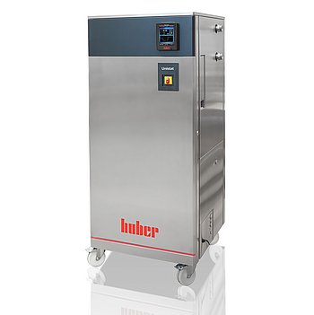
Peter Huber Kältemaschinenbau Unistat GL 540w Dynamisches
Peter Huber Kältemaschinenbau Unistat GL 540w Dynamisches — Temperature control units.
The Unistat GL 540w Dynamisches is a water-cooled, CO2 (R-744) refrigerant temperature control unit with a magnetically coupled stainless-steel pump, covering -50 to 200 °C with 12 kW heating. Its 196 l/min zero-head pump and M38x1.5 process connection distinguish it within the Unistat 5xx w series for high-flow, high-pressure-drop loops.
Peter Huber Kältemaschinenbau Unistat Series — Model Comparison & Selection
| Model | Noise level, dB | Display resolution | Heating capacity, W | Pump connection | Pump type | Temperature range, °C |
|---|---|---|---|---|---|---|
| Unistat GL 540w Dynamisches Current | — | 0, 01 | 12000 | M38x1, 5 AG male | magnetically coupled, st | -50–200 |
| Unistat 510w Dynamisches | 60 | 0, 01 | 6000 | M30x1, 5 AG male | magnetically coupled, st | -50–250 |
| Unistat 515w Dynamisches | — | 0, 01 | 6000 | M30x1, 5 AG male | magnetically coupled, st | -50–250 |
| Unistat 520w Dynamisches | 61 | 0, 01 | 6000 | M30x1, 5 AG male | magnetically coupled, st | -55–250 |
| Unistat 525 Dynamisches | 56 | 0, 01 | 6000 | M30x1, 5 AG male | magnetically coupled, st | -55–250 |
| Unistat 525w Dynamisches | 61 | 0, 01 | 6000 | M30x1, 5 AG male | magnetically coupled, st | -55–250 |
| Unistat 527w Dynamisches | — | 0, 01 | 12000 | M38x1, 5 AG male | magnetically coupled, st | -55–250 |
| Unistat 530w Dynamisches | 59 | 0, 01 | 12000 | M38x1, 5 AG male | magnetically coupled, st | -55–250 |
| Unistat 540w Dynamisches | — | 0, 01 | 24000 | M38x1, 5 AG male | magnetically coupled, st | -55–250 |
| Unistat 545w Dynamisches | — | 0, 01 | 24000 | M38x1, 5 AG male | magnetically coupled, st | -55–250 |
| Unistat 610w Dynamisches | 62 | 0, 01 | 6000 | M30x1, 5 AG male | magnetically coupled, st | -60–200 |
| Unistat 615w Dynamisches | 62 | 0, 01 | 12000 | M30x1, 5 AG male | Pressure pump, variable | -60–200 |
| Unistat 620w Dynamisches | 68 | 0, 01 | 12000 | M38x1, 5 AG male | magnetically coupled, st | -60–200 |
| Unistat 625w Dynamisches | — | 0, 01 | 12000 | M38x1, 5 AG male | magnetically coupled, st | -60–200 |
| Unistat 630w Dynamisches | — | 0, 01 | 24000 | M38x1, 5 AG male | magnetically coupled, st | -60–200 |
| Unistat 635w Dynamisches | — | 0, 01 | 24000 | M38x1, 5 AG male | magnetically coupled, st | -60–200 |
| Unistat 640w Dynamisches | — | 0, 01 | 24000 | M38x1, 5 AG male | magnetically coupled, st | -60–200 |
| Unistat 645w Dynamisches | — | 0, 01 | 36000 | flange DN32 PN10/40 EN10 | magnetically coupled, st | -60–200 |
| Unistat 650w Dynamisches | 73 | 0, 01 | 48000 | flange DN32 PN10/40 EN10 | magnetically coupled, st | -60–200 |
| Unistat 680w Dynamisches | — | 0, 01 | 96000 | DN50 PN16 (DIN EN 1092-1 | magnetically coupled, st | -60–200 |
| Unistat GL 530w Dynamisches | 61 | 0, 01 | 6000 | M38x1, 5 AG male | magnetically coupled, st | -50–200 |
| Unistat GL 535w Dynamisches | — | 0, 01 | 12000 | M38x1, 5 AG male | magnetically coupled, st | -50–200 |
| Unistat GL 550w Dynamisches | — | 0, 01 | 24000 | M38x1, 5 AG male | magnetically coupled, st | -50–200 |
| Unistat GL 560w Dynamisches | — | 0, 01 | 24000 | M38x1, 5 AG male | magnetically coupled, st | -50–200 |
| Unistat GL 570w Dynamisches | — | 0, 01 | 48000 | M38x1, 5 AG male | magnetically coupled, st | -50–200 |
| Unistat GL P530w Dynamisches | 61 | 0, 01 | 6000 | M38x1, 5 AG male | magnetically coupled, st | -50–200 |
| Unistat GL P535w Dynamisches | — | 0, 01 | 12000 | M38x1, 5 AG male | magnetically coupled, st | -50–200 |
| Unistat GL P540w Dynamisches | — | 0, 01 | 12000 | M38x1, 5 AG male | magnetically coupled, st | -50–200 |
| Unistat GL P550w Dynamisches | — | 0, 01 | 24000 | M38x1, 5 AG male | magnetically coupled, st | -50–200 |
| Unistat GL P560w Dynamisches | — | 0, 01 | 24000 | M38x1, 5 AG male | magnetically coupled, st | -50–200 |
| Unistat GL P570w Dynamisches | — | 0, 01 | 48000 | M38x1, 5 AG male | magnetically coupled, st | -50–200 |
| Unistat P510 Dynamisches | 60 | 0, 01 | 6000 | M30x1, 5 AG male | magnetically coupled, st | -50–250 |
| Unistat P510w Dynamisches | 60 | 0, 01 | 6000 | M30x1, 5 AG male | magnetically coupled, st | -50–250 |
| Unistat P515w Dynamisches | — | 0, 01 | 6000 | M30x1, 5 AG male | magnetically coupled, st | -50–250 |
| Unistat P520 Dynamisches | — | 0, 01 | 6000 | M30x1, 5 AG male | magnetically coupled, st | -55–250 |
| Unistat P520w Dynamisches | 61 | 0, 01 | 6000 | M30x1, 5 AG male | magnetically coupled, st | -55–250 |
| Unistat P525 Dynamisches | 56 | 0, 01 | 6000 | M30x1, 5 AG male | magnetically coupled, st | -55–250 |
| Unistat P525w Dynamisches | 61 | 0, 01 | 6000 | M30x1, 5 AG male | magnetically coupled, st | -55–250 |
| Unistat P527w Dynamisches | 57 | 0, 01 | 12000 | M38x1, 5 AG male | magnetically coupled, st | -55–250 |
| Unistat P530w Dynamisches | 62 | 0.01 | 12000 | M38x1,5 AG male | magnetically coupled, st | -55–250 |
| Unistat P540w Dynamisches | — | 0, 01 | 24000 | M38x1, 5 AG male | magnetically coupled, st | -55–250 |
| Unistat P545w Dynamisches | — | 0, 01 | 24000 | M38x1, 5 AG male | magnetically coupled, st | -55–250 |
| Unistat P610 Dynamisches | — | 0, 01 | 6000 | M30x1, 5 AG male | magnetically coupled, st | -60–200 |
| Unistat P610w Dynamisches | 62 | 0, 01 | 6000 | M30x1, 5 AG male | magnetically coupled, st | -60–200 |
| Unistat P615 Dynamisches | — | 0, 01 | 12000 | M30x1, 5 AG male | magnetically coupled, st | -60–200 |
| Unistat P615w Dynamisches | 62 | 0, 01 | 12000 | M30x1, 5 AG male | magnetically coupled, st | -60–200 |
| Unistat P620w Dynamisches | — | 0, 01 | 12000 | M38x1, 5 AG male | magnetically coupled, st | -60–200 |
| Unistat P625w Dynamisches | — | 0, 01 | 12000 | M38x1, 5 AG male | magnetically coupled, st | -60–200 |
| Unistat P630w Dynamisches | — | 0, 01 | 24000 | M38x1, 5 AG male | magnetically coupled, st | -60–200 |
| Unistat P635w Dynamisches | — | 0, 01 | 24000 | M38x1, 5 AG male | magnetically coupled, st | -60–200 |
| Unistat P645w Dynamisches | — | 0, 01 | 36000 | flange DN32 PN10/40 EN10 | magnetically coupled, st | -60–200 |
| Unistat P650w Dynamisches | — | 0, 01 | 48000 | flange DN32 PN10/40 EN10 | magnetically coupled, st | -60–200 |
Full specifications
| Control output | POKO ONE |
| Heating capacity | 12 kW |
| Pump connection | M38x1, 5 AG male |
| Pump speed adjustable | Yes |
| Pump type | magnetically coupled, stainless steel |
| External sensor connection | Pt100 |
| Temperature range | -50...200 °C |
| Power supply | 400V 3~ 50Hz |
| Controller | Pilot ONE |
| Display resolution | 0, 01 K |
| Digital interface | Ethernet, USB (Host u. Device), RS232 |
| Maximum viscosity | 100 mm²/s |
| Ambient temperature limit | 5...40 °C |
| Cooling water connection | G3/4 male |
| Cooling water differential pressure | 1 bar (min) |
| Cooling Water Pressure | 6 bar (max) |
| Protection rating | IP20 |
| Safety class | III / FL |
Description
Construction and series positioning
- Free-standing water-cooled unit (suffix 'w') using R-744 refrigerant; the 'GL' designation denotes CO2 refrigerant rather than the air-cooled base variant.
- Sibling models in the 5xx w Dynamisches family (510w, 515w, 520w, 525) share the dynamic temperature control architecture; this GL 540w adds CO2 refrigerant and the larger 12 kW heater / 28 kW cooling class.
- Process circuit: magnetically coupled stainless-steel pump, speed-adjustable, with M38x1.5 male pump connection; cooling water connection G3/4 male.
- Controller: Pilot ONE with POKO ONE control output; display resolution 0.01 K; interfaces Ethernet, USB host/device, RS232; external Pt100 sensor input.
Behavior under load and media
- Temperature range -50 to 200 °C; heating capacity 12 kW. Published cooling power is valid only at 20 °C room temperature, 15 °C cooling water inlet and 1 bar differential pressure.
- Pump curve: 196 l/min at zero head, falling to 86 l/min at 2.0 bar; external circuit pressure drop therefore sets the achievable flow.
- Heat transfer fluid kinematic viscosity must not exceed 100 mm²/s; minimum filling capacity 8.9 l, expansion tank 19.9 l.
- Safety classification III / FL per DIN 12876; overtemperature protection adjustable; 'Process safety' mode releases maximum cooling at the OT trigger instead of all-pole switch-off.
Installation, control and operation
- Requires 400 V 3~ 50 Hz supply; three-phase units below 63 A are delivered with cable but without plug, so final connection is by the customer's electrician.
- Cooling water: 1–4 bar differential pressure, maximum 6 bar static, inlet temperature 5–20 °C; insulate pipes if condensation occurs.
- IP20; ambient 5–40 °C; overall dimensions 918x963x1771 mm; leveling feet/caster brakes must be set before commissioning; allow ~2 h acclimation after cold/warm moves.
- Expansion vessel must remain unlocked for externally closed applications and locked for externally open (bath) applications.
- Cooling water supply should be shut off during downtimes, including overnight.
Integration & Operating Notes
The unit needs a 400 V 3~ 50 Hz supply sized for the 12 kW heater and 28 kW cooling load. Voltage tolerance is ±5% only with simultaneous frequency tolerance of ±2%, and certain combinations are explicitly not allowed; verify site power quality before connection. Three-phase devices below 63 A arrive with cable but no plug, so the customer must provide the final disconnect and connection.
Cooling water must be supplied at 1–4 bar differential pressure and no more than 6 bar static, with inlet temperature between 5 °C and 20 °C. The 28 kW cooling rating is valid only at 20 °C room temperature, 15 °C cooling water inlet and 1 bar differential pressure; outside these conditions the capacity cannot be assumed and condensation risk rises, requiring pipe insulation.
Maximum permissible kinematic viscosity of the heat transfer fluid is 100 mm²/s. Selecting a fluid that exceeds this at low temperature can overload the magnetically coupled pump and degrade heat transfer. Minimum filling capacity is 8.9 l and the expansion tank holds 19.9 l, so external loop volume and expansion allowance must be checked against these figures.
Leveling feet must be unscrewed/activated and caster parking brakes engaged before commissioning. Allow about 2 hours acclimation when moving between cold and warm environments before power-on to avoid condensation-induced electrical faults. For externally closed applications the expansion vessel must remain unlocked; locking it causes overpressure damage. For externally open (bath) applications it must be locked to prevent fluid loss.
Shut off the cooling water supply even for short downtimes such as overnight to prevent water damage and unnecessary load on the circuit. Hoses and hose connections must be periodically checked for leaks and quality and replaced as needed. Work on the coolant circuit must be carried out by approved refrigeration/air-conditioning contractors; refrigerant handling is not a general-maintenance task.
The Pilot ONE can be set to 'Off/Standby' (default, temperature control started only by manual input) or 'ON/Temperature control active' (automatic restart after power restoration, with a brief INFO allowing cancellation). Select according to whether unattended restart is acceptable for the process. In 'Process safety' mode the compressor must be set to Permanently ON so maximum cooling is released at the OT trigger instead of all-pole switch-off.
Selection & Integration Q&A
Pick the GL 540w when you need CO2 (R-744) refrigerant, the 12 kW heater class and the 196 l/min zero-head pump for high-flow or high-pressure-drop loops. The smaller 5xx w Dynamisches siblings suit lower heat loads or where CO2 refrigerant is not required.
The process circuit uses an M38x1.5 male pump connection; the cooling water side uses G3/4 male. Mating hoses and adapters must be ordered accordingly. External circuit pressure drop sets achievable flow: 196 l/min at zero head falls to 86 l/min at 2.0 bar.
Install at 5–40 °C ambient, IP20 (dry, non-condensing), outside any ATEX zone. Cooling water inlet 5–20 °C, 1–4 bar differential, max 6 bar static. Shut off cooling water during downtimes including overnight; allow ~2 h acclimation after cold/warm moves.
Three-phase units below 63 A ship with cable but without a plug; the customer provides the final connection. A drip tray for condensation/heat transfer fluid must be installed by the responsible body. Refrigerant-circuit work requires approved contractors; hoses and fluid are inspected/replaced on schedule.