
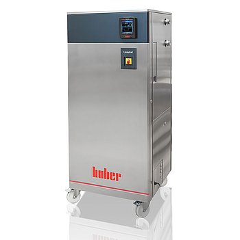
Peter Huber Kältemaschinenbau Unistat GL P540w Dynamisches
Peter Huber Kältemaschinenbau Unistat GL P540w Dynamisches — Temperature control units.
The Unistat GL P540w Dynamisches is a water-cooled, CO2-refrigerant (GL) temperature control unit with a magnetically coupled stainless-steel pump, rated for -50 to 200 °C and 12 kW heating on a 400 V 3~ 50 Hz supply. Its 'P' designation targets applications with high pressure drop, and the 'Dynamisches' variant is built for dynamic temperature ramps. It serves as a circulation source for externally closed process loops requiring high pump pressure and wide temperature span.
Peter Huber Kältemaschinenbau Unistat Series — Model Comparison & Selection
| Model | Noise level, dB | Display resolution | Heating capacity, W | Pump connection | Pump type | Temperature range, °C |
|---|---|---|---|---|---|---|
| Unistat GL P540w Dynamisches Current | — | 0, 01 | 12000 | M38x1, 5 AG male | magnetically coupled, st | -50–200 |
| Unistat 510w Dynamisches | 60 | 0, 01 | 6000 | M30x1, 5 AG male | magnetically coupled, st | -50–250 |
| Unistat 515w Dynamisches | — | 0, 01 | 6000 | M30x1, 5 AG male | magnetically coupled, st | -50–250 |
| Unistat 520w Dynamisches | 61 | 0, 01 | 6000 | M30x1, 5 AG male | magnetically coupled, st | -55–250 |
| Unistat 525 Dynamisches | 56 | 0, 01 | 6000 | M30x1, 5 AG male | magnetically coupled, st | -55–250 |
| Unistat 525w Dynamisches | 61 | 0, 01 | 6000 | M30x1, 5 AG male | magnetically coupled, st | -55–250 |
| Unistat 527w Dynamisches | — | 0, 01 | 12000 | M38x1, 5 AG male | magnetically coupled, st | -55–250 |
| Unistat 530w Dynamisches | 59 | 0, 01 | 12000 | M38x1, 5 AG male | magnetically coupled, st | -55–250 |
| Unistat 540w Dynamisches | — | 0, 01 | 24000 | M38x1, 5 AG male | magnetically coupled, st | -55–250 |
| Unistat 545w Dynamisches | — | 0, 01 | 24000 | M38x1, 5 AG male | magnetically coupled, st | -55–250 |
| Unistat 610w Dynamisches | 62 | 0, 01 | 6000 | M30x1, 5 AG male | magnetically coupled, st | -60–200 |
| Unistat 615w Dynamisches | 62 | 0, 01 | 12000 | M30x1, 5 AG male | Pressure pump, variable | -60–200 |
| Unistat 620w Dynamisches | 68 | 0, 01 | 12000 | M38x1, 5 AG male | magnetically coupled, st | -60–200 |
| Unistat 625w Dynamisches | — | 0, 01 | 12000 | M38x1, 5 AG male | magnetically coupled, st | -60–200 |
| Unistat 630w Dynamisches | — | 0, 01 | 24000 | M38x1, 5 AG male | magnetically coupled, st | -60–200 |
| Unistat 635w Dynamisches | — | 0, 01 | 24000 | M38x1, 5 AG male | magnetically coupled, st | -60–200 |
| Unistat 640w Dynamisches | — | 0, 01 | 24000 | M38x1, 5 AG male | magnetically coupled, st | -60–200 |
| Unistat 645w Dynamisches | — | 0, 01 | 36000 | flange DN32 PN10/40 EN10 | magnetically coupled, st | -60–200 |
| Unistat 650w Dynamisches | 73 | 0, 01 | 48000 | flange DN32 PN10/40 EN10 | magnetically coupled, st | -60–200 |
| Unistat 680w Dynamisches | — | 0, 01 | 96000 | DN50 PN16 (DIN EN 1092-1 | magnetically coupled, st | -60–200 |
| Unistat GL 530w Dynamisches | 61 | 0, 01 | 6000 | M38x1, 5 AG male | magnetically coupled, st | -50–200 |
| Unistat GL 535w Dynamisches | — | 0, 01 | 12000 | M38x1, 5 AG male | magnetically coupled, st | -50–200 |
| Unistat GL 540w Dynamisches | — | 0, 01 | 12000 | M38x1, 5 AG male | magnetically coupled, st | -50–200 |
| Unistat GL 550w Dynamisches | — | 0, 01 | 24000 | M38x1, 5 AG male | magnetically coupled, st | -50–200 |
| Unistat GL 560w Dynamisches | — | 0, 01 | 24000 | M38x1, 5 AG male | magnetically coupled, st | -50–200 |
| Unistat GL 570w Dynamisches | — | 0, 01 | 48000 | M38x1, 5 AG male | magnetically coupled, st | -50–200 |
| Unistat GL P530w Dynamisches | 61 | 0, 01 | 6000 | M38x1, 5 AG male | magnetically coupled, st | -50–200 |
| Unistat GL P535w Dynamisches | — | 0, 01 | 12000 | M38x1, 5 AG male | magnetically coupled, st | -50–200 |
| Unistat GL P550w Dynamisches | — | 0, 01 | 24000 | M38x1, 5 AG male | magnetically coupled, st | -50–200 |
| Unistat GL P560w Dynamisches | — | 0, 01 | 24000 | M38x1, 5 AG male | magnetically coupled, st | -50–200 |
| Unistat GL P570w Dynamisches | — | 0, 01 | 48000 | M38x1, 5 AG male | magnetically coupled, st | -50–200 |
| Unistat P510 Dynamisches | 60 | 0, 01 | 6000 | M30x1, 5 AG male | magnetically coupled, st | -50–250 |
| Unistat P510w Dynamisches | 60 | 0, 01 | 6000 | M30x1, 5 AG male | magnetically coupled, st | -50–250 |
| Unistat P515w Dynamisches | — | 0, 01 | 6000 | M30x1, 5 AG male | magnetically coupled, st | -50–250 |
| Unistat P520 Dynamisches | — | 0, 01 | 6000 | M30x1, 5 AG male | magnetically coupled, st | -55–250 |
| Unistat P520w Dynamisches | 61 | 0, 01 | 6000 | M30x1, 5 AG male | magnetically coupled, st | -55–250 |
| Unistat P525 Dynamisches | 56 | 0, 01 | 6000 | M30x1, 5 AG male | magnetically coupled, st | -55–250 |
| Unistat P525w Dynamisches | 61 | 0, 01 | 6000 | M30x1, 5 AG male | magnetically coupled, st | -55–250 |
| Unistat P527w Dynamisches | 57 | 0, 01 | 12000 | M38x1, 5 AG male | magnetically coupled, st | -55–250 |
| Unistat P530w Dynamisches | 62 | 0.01 | 12000 | M38x1,5 AG male | magnetically coupled, st | -55–250 |
| Unistat P540w Dynamisches | — | 0, 01 | 24000 | M38x1, 5 AG male | magnetically coupled, st | -55–250 |
| Unistat P545w Dynamisches | — | 0, 01 | 24000 | M38x1, 5 AG male | magnetically coupled, st | -55–250 |
| Unistat P610 Dynamisches | — | 0, 01 | 6000 | M30x1, 5 AG male | magnetically coupled, st | -60–200 |
| Unistat P610w Dynamisches | 62 | 0, 01 | 6000 | M30x1, 5 AG male | magnetically coupled, st | -60–200 |
| Unistat P615 Dynamisches | — | 0, 01 | 12000 | M30x1, 5 AG male | magnetically coupled, st | -60–200 |
| Unistat P615w Dynamisches | 62 | 0, 01 | 12000 | M30x1, 5 AG male | magnetically coupled, st | -60–200 |
| Unistat P620w Dynamisches | — | 0, 01 | 12000 | M38x1, 5 AG male | magnetically coupled, st | -60–200 |
| Unistat P625w Dynamisches | — | 0, 01 | 12000 | M38x1, 5 AG male | magnetically coupled, st | -60–200 |
| Unistat P630w Dynamisches | — | 0, 01 | 24000 | M38x1, 5 AG male | magnetically coupled, st | -60–200 |
| Unistat P635w Dynamisches | — | 0, 01 | 24000 | M38x1, 5 AG male | magnetically coupled, st | -60–200 |
| Unistat P645w Dynamisches | — | 0, 01 | 36000 | flange DN32 PN10/40 EN10 | magnetically coupled, st | -60–200 |
| Unistat P650w Dynamisches | — | 0, 01 | 48000 | flange DN32 PN10/40 EN10 | magnetically coupled, st | -60–200 |
Full specifications
| Control output | POKO ONE |
| Heating capacity | 12 kW |
| Pump connection | M38x1, 5 AG male |
| Pump speed adjustable | Yes |
| Pump type | magnetically coupled, stainless steel |
| External sensor connection | Pt100 |
| Temperature range | -50...200 °C |
| Power supply | 400V 3~ 50Hz |
| Controller | Pilot ONE |
| Display resolution | 0, 01 K |
| Digital interface | Ethernet, USB (Host u. Device), RS232 |
| Maximum viscosity | 100 mm²/s |
| Ambient temperature limit | 5...40 °C |
| Cooling water connection | G3/4 male |
| Cooling water differential pressure | 1 bar (min) |
| Cooling Water Pressure | 6 bar (max) |
| Protection rating | IP20 |
| Safety class | III / FL |
Description
Construction and series positioning
- Water-cooled refrigeration circuit using natural refrigerant R-744 (GWP 1); model suffix 'GL' denotes CO2 refrigerant, 'w' water cooling, 'P' high-pressure-drop applications, 'Dynamisches' dynamic duty.
- Magnetically coupled stainless-steel pump with adjustable speed; pump connection M38x1.5 male, cooling water connections G3/4 male.
- Controller: Pilot ONE with POKO ONE control output; interfaces Ethernet, USB host/device, RS232; external Pt100 sensor input.
- Safety class III/FL with adjustable overtemperature protection per DIN 12876; IP20 enclosure.
- Sibling models in the Unistat 5xx dynamic series (510w, 515w, 520w, 525) differ in size/performance; this P540w is the high-pressure-drop modification.
Behavior under load and media
- Temperature range -50 to 200 °C; heating capacity 12 kW. Cooling performance is rated at 20 °C room, 15 °C cooling water inlet and 1 bar differential, so capacity derates if site water is warmer or differential pressure lower.
- Pump delivers up to 201 l/min at 5.3 bar max, dropping to 42 l/min at 5.0 bar; system pressure drop must be checked against this curve.
- Viscosity limit 100 mm²/s for the heat transfer fluid; minimum filling 8.9 l, expansion tank 19.9 l.
- Cooling water circuit materials include copper, stainless steel 1.4401, MS, PA, PPE, PTFE and EPDM; only compatible water may be used. If cooling water is below the condensation point, internal cooling water pipes must be insulated.
Installation, control and operation
- Requires 400 V 3~ 50 Hz supply; three-phase units under 63 A are delivered with cable but without plug. Voltage tolerance ±5% only with frequency ±2%, and -5% voltage with +2% frequency is not allowed.
- Cooling water: 1–4 bar differential (min 1 bar, max 4 bar), max 6 bar, 5–20 °C inlet.
- Ambient 5–40 °C; IP20 requires dry indoor location. Unit must not be installed in an ATEX zone.
- Pilot ONE offers Process Safety mode (releases max cooling at OT trigger instead of switching off), Power Failure Auto restart option, and Delta T limiter. For externally closed applications the expansion vessel must remain unlocked; for open bath applications it must be locked.
- Maintenance includes cleaning liquefier fins, hat-type strainer, drip tray, and periodic hose inspection; cooling water should be shut off during downtimes.
Integration & Operating Notes
The unit accepts 400 V 3~ 50 Hz with ±5% voltage only when frequency is also within ±2%; combinations such as -5% voltage with +2% frequency are explicitly not allowed. Verify grid quality at the installation point before connection, as out-of-tolerance supply can fault the compressor and electronics.
Rated cooling is stated at 1 bar differential and 15 °C inlet; the facility loop must provide at least 1 bar differential but not exceed 4 bar differential or 6 bar static pressure. Insufficient differential prevents rated cooling, while excessive pressure can damage the internal circuit. Intake water must be 5–20 °C.
For externally closed applications, locking the expansion vessel will damage the application due to overpressure. For externally open (bath) applications the vessel must be locked to prevent fluid loss. Confirm the application type before commissioning and set the isolating valve accordingly.
In Process Safety mode the controller releases maximum cooling capacity at the overtemperature trigger instead of switching off all poles. This mode only functions correctly if the compressor is configured to Permanently ON; otherwise the protective cooling action is not available. Configure this before relying on the function for exothermic processes.
When the unit is moved between cold and warm environments, condensation can form on electrical components. Allow approximately 2 hours acclimation before power-on to prevent short circuits or corrosion. Also transport only upright and only when emptied.
The manual directs shutting off the cooling water supply even for short downtimes such as overnight. This prevents unnecessary load on the cooling water circuit and reduces risk of water damage from pressure surges or leaks while unattended.
Three-phase devices with current consumption less than 63 A are delivered with a cable but without a plug. A suitable plug must be sourced and fitted on site by an electrician, and the connection must match the rating plate voltage and frequency.
Selection & Integration Q&A
Choose the P540w when the process loop has high pressure drop and needs the 'P' high-pressure pump variant plus CO2 refrigerant (GL). The 510w/520w are air-cooled siblings without the P designation; select them for lower pressure-drop loops where water cooling is not available.
Provide 5–20 °C water at 1–4 bar differential (max 6 bar static) with G3/4 male connections. The process pump connection is M38x1.5 male, so mating hoses and adapters must be ordered separately. Insulate internal cooling water pipes if water is below the condensation point.
Install indoors, dry, IP20, ambient 5–40 °C, never in an ATEX zone. Transport upright and emptied; allow 2 h acclimation after cold/warm moves. Leveling feet or caster brakes must be engaged before start-up. A drip tray is required below the unit.
The base delivery excludes the three-phase plug (cable only), mating hoses/adapters for G3/4 and M38x1.5, and a drip tray. Periodic tasks include cleaning liquefier fins and the hat-type strainer, inspecting hoses, and replacing heat transfer fluid per manual; cooling water should be shut off during downtimes.