
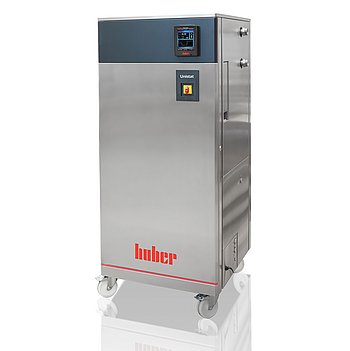
Peter Huber Kältemaschinenbau Unistat GL P570w Dynamisches
Peter Huber Kältemaschinenbau Unistat GL P570w Dynamisches — Temperature control units.
The Unistat GL P570w Dynamisches is a water-cooled, CO2-refrigerant (GL) high-capacity temperature control unit with magnetically coupled stainless-steel pump, covering -50 to 200 °C with 48 kW heating. Its M38x1.5 pump connection and 201 l/min / 5.3 bar delivery distinguish it from smaller siblings for high-pressure-drop external circuits.
Peter Huber Kältemaschinenbau Unistat Series — Model Comparison & Selection
| Model | Noise level, dB | Display resolution | Heating capacity, W | Pump connection | Pump type | Temperature range, °C |
|---|---|---|---|---|---|---|
| Unistat GL P570w Dynamisches Current | — | 0, 01 | 48000 | M38x1, 5 AG male | magnetically coupled, st | -50–200 |
| Unistat 510w Dynamisches | 60 | 0, 01 | 6000 | M30x1, 5 AG male | magnetically coupled, st | -50–250 |
| Unistat 515w Dynamisches | — | 0, 01 | 6000 | M30x1, 5 AG male | magnetically coupled, st | -50–250 |
| Unistat 520w Dynamisches | 61 | 0, 01 | 6000 | M30x1, 5 AG male | magnetically coupled, st | -55–250 |
| Unistat 525 Dynamisches | 56 | 0, 01 | 6000 | M30x1, 5 AG male | magnetically coupled, st | -55–250 |
| Unistat 525w Dynamisches | 61 | 0, 01 | 6000 | M30x1, 5 AG male | magnetically coupled, st | -55–250 |
| Unistat 527w Dynamisches | — | 0, 01 | 12000 | M38x1, 5 AG male | magnetically coupled, st | -55–250 |
| Unistat 530w Dynamisches | 59 | 0, 01 | 12000 | M38x1, 5 AG male | magnetically coupled, st | -55–250 |
| Unistat 540w Dynamisches | — | 0, 01 | 24000 | M38x1, 5 AG male | magnetically coupled, st | -55–250 |
| Unistat 545w Dynamisches | — | 0, 01 | 24000 | M38x1, 5 AG male | magnetically coupled, st | -55–250 |
| Unistat 610w Dynamisches | 62 | 0, 01 | 6000 | M30x1, 5 AG male | magnetically coupled, st | -60–200 |
| Unistat 615w Dynamisches | 62 | 0, 01 | 12000 | M30x1, 5 AG male | Pressure pump, variable | -60–200 |
| Unistat 620w Dynamisches | 68 | 0, 01 | 12000 | M38x1, 5 AG male | magnetically coupled, st | -60–200 |
| Unistat 625w Dynamisches | — | 0, 01 | 12000 | M38x1, 5 AG male | magnetically coupled, st | -60–200 |
| Unistat 630w Dynamisches | — | 0, 01 | 24000 | M38x1, 5 AG male | magnetically coupled, st | -60–200 |
| Unistat 635w Dynamisches | — | 0, 01 | 24000 | M38x1, 5 AG male | magnetically coupled, st | -60–200 |
| Unistat 640w Dynamisches | — | 0, 01 | 24000 | M38x1, 5 AG male | magnetically coupled, st | -60–200 |
| Unistat 645w Dynamisches | — | 0, 01 | 36000 | flange DN32 PN10/40 EN10 | magnetically coupled, st | -60–200 |
| Unistat 650w Dynamisches | 73 | 0, 01 | 48000 | flange DN32 PN10/40 EN10 | magnetically coupled, st | -60–200 |
| Unistat 680w Dynamisches | — | 0, 01 | 96000 | DN50 PN16 (DIN EN 1092-1 | magnetically coupled, st | -60–200 |
| Unistat GL 530w Dynamisches | 61 | 0, 01 | 6000 | M38x1, 5 AG male | magnetically coupled, st | -50–200 |
| Unistat GL 535w Dynamisches | — | 0, 01 | 12000 | M38x1, 5 AG male | magnetically coupled, st | -50–200 |
| Unistat GL 540w Dynamisches | — | 0, 01 | 12000 | M38x1, 5 AG male | magnetically coupled, st | -50–200 |
| Unistat GL 550w Dynamisches | — | 0, 01 | 24000 | M38x1, 5 AG male | magnetically coupled, st | -50–200 |
| Unistat GL 560w Dynamisches | — | 0, 01 | 24000 | M38x1, 5 AG male | magnetically coupled, st | -50–200 |
| Unistat GL 570w Dynamisches | — | 0, 01 | 48000 | M38x1, 5 AG male | magnetically coupled, st | -50–200 |
| Unistat GL P530w Dynamisches | 61 | 0, 01 | 6000 | M38x1, 5 AG male | magnetically coupled, st | -50–200 |
| Unistat GL P535w Dynamisches | — | 0, 01 | 12000 | M38x1, 5 AG male | magnetically coupled, st | -50–200 |
| Unistat GL P540w Dynamisches | — | 0, 01 | 12000 | M38x1, 5 AG male | magnetically coupled, st | -50–200 |
| Unistat GL P550w Dynamisches | — | 0, 01 | 24000 | M38x1, 5 AG male | magnetically coupled, st | -50–200 |
| Unistat GL P560w Dynamisches | — | 0, 01 | 24000 | M38x1, 5 AG male | magnetically coupled, st | -50–200 |
| Unistat P510 Dynamisches | 60 | 0, 01 | 6000 | M30x1, 5 AG male | magnetically coupled, st | -50–250 |
| Unistat P510w Dynamisches | 60 | 0, 01 | 6000 | M30x1, 5 AG male | magnetically coupled, st | -50–250 |
| Unistat P515w Dynamisches | — | 0, 01 | 6000 | M30x1, 5 AG male | magnetically coupled, st | -50–250 |
| Unistat P520 Dynamisches | — | 0, 01 | 6000 | M30x1, 5 AG male | magnetically coupled, st | -55–250 |
| Unistat P520w Dynamisches | 61 | 0, 01 | 6000 | M30x1, 5 AG male | magnetically coupled, st | -55–250 |
| Unistat P525 Dynamisches | 56 | 0, 01 | 6000 | M30x1, 5 AG male | magnetically coupled, st | -55–250 |
| Unistat P525w Dynamisches | 61 | 0, 01 | 6000 | M30x1, 5 AG male | magnetically coupled, st | -55–250 |
| Unistat P527w Dynamisches | 57 | 0, 01 | 12000 | M38x1, 5 AG male | magnetically coupled, st | -55–250 |
| Unistat P530w Dynamisches | 62 | 0.01 | 12000 | M38x1,5 AG male | magnetically coupled, st | -55–250 |
| Unistat P540w Dynamisches | — | 0, 01 | 24000 | M38x1, 5 AG male | magnetically coupled, st | -55–250 |
| Unistat P545w Dynamisches | — | 0, 01 | 24000 | M38x1, 5 AG male | magnetically coupled, st | -55–250 |
| Unistat P610 Dynamisches | — | 0, 01 | 6000 | M30x1, 5 AG male | magnetically coupled, st | -60–200 |
| Unistat P610w Dynamisches | 62 | 0, 01 | 6000 | M30x1, 5 AG male | magnetically coupled, st | -60–200 |
| Unistat P615 Dynamisches | — | 0, 01 | 12000 | M30x1, 5 AG male | magnetically coupled, st | -60–200 |
| Unistat P615w Dynamisches | 62 | 0, 01 | 12000 | M30x1, 5 AG male | magnetically coupled, st | -60–200 |
| Unistat P620w Dynamisches | — | 0, 01 | 12000 | M38x1, 5 AG male | magnetically coupled, st | -60–200 |
| Unistat P625w Dynamisches | — | 0, 01 | 12000 | M38x1, 5 AG male | magnetically coupled, st | -60–200 |
| Unistat P630w Dynamisches | — | 0, 01 | 24000 | M38x1, 5 AG male | magnetically coupled, st | -60–200 |
| Unistat P635w Dynamisches | — | 0, 01 | 24000 | M38x1, 5 AG male | magnetically coupled, st | -60–200 |
| Unistat P645w Dynamisches | — | 0, 01 | 36000 | flange DN32 PN10/40 EN10 | magnetically coupled, st | -60–200 |
| Unistat P650w Dynamisches | — | 0, 01 | 48000 | flange DN32 PN10/40 EN10 | magnetically coupled, st | -60–200 |
Full specifications
| Alarm output | optic, acoustic, relay |
| Control output | POKO ONE |
| Heating capacity | 48 kW |
| Maximum delivery flow rate | 201 l/min (pressure pump max; also 5, 3 bar) |
| Pump connection | M38x1, 5 AG male |
| Pump speed adjustable | Yes |
| Pump type | magnetically coupled, stainless steel |
| External sensor connection | Pt100 |
| Temperature range | -50...200 °C |
| Power supply | 400V 3~ 50Hz |
| Controller | Pilot ONE |
| Display resolution | 0, 01 K |
| Digital interface | Ethernet, USB (Host u. Device), RS232 |
| Maximum viscosity | 100 mm²/s |
| Ambient temperature limit | 5...40 °C |
| Cooling water connection | G3/4 male |
| Cooling water differential pressure | 1 bar (min) |
| Cooling Water Pressure | 6 bar (max) |
| Protection rating | IP20 |
| Safety class | III / FL |
Description
Construction and series positioning
- Water-cooled (w) Unistat with CO2 refrigerant (GL) and dynamic pressure pump (P) for high pressure-drop applications; Pilot ONE controller with POKO ONE control output.
- Sits above the Unistat 5xx Dynamisches siblings (510w, 515w, 520w, 525) in heating capacity and flow; those lack the GL CO2 refrigerant designation.
- Stainless-steel, magnetically coupled circulation pump with adjustable speed; M38x1.5 male pump connection requires ball socket per DIN 3863 and sleeve nut per DIN 3870.
Working range and media behavior
- Temperature range -50 to 200 °C; heating capacity 48 kW; max delivery 201 l/min at max 5.3 bar delivery pressure, with flow decreasing as pressure rises.
- Heat transfer fluid max kinematic viscosity 100 mm²/s; FL safety class requires fire point ≥65 °C (ethanol only under supervision).
- Water-cooled: cooling water 5–20 °C intake, G3/4 male connection, differential pressure 1–4 bar, max pressure 6 bar; cooling capacity falls and flow demand rises as cooling water temperature increases. Insulate cooling water pipes below condensation point.
Installation, control and operation
- 400 V 3~ 50 Hz supply, ±5% voltage with ±2% frequency (invalid combinations such as -5% V with +2% Hz not allowed); three-phase units under 63 A come with cable but no plug; hard-wiring by an electrician.
- Pilot ONE touchscreen with Ethernet, USB host/device, RS232; Pt100 external sensor input; alarm via optic, acoustic and relay.
- IP20, ambient 5–40 °C; not for ATEX zones, medical devices or direct food contact; drip tray required below unit.
Integration & Operating Notes
Horizontal transport damages the compressor, and a filled unit risks thermal fluid overflow during relocation. Casters are not for transport and carry only 25% of total mass symmetrically; use an industrial truck. Leveling feet must be activated and parking brakes engaged before commissioning.
Voltage tolerance is ±5% with simultaneous frequency tolerance ±2%, but combinations such as -5% voltage with +2% frequency are not allowed. Three-phase devices under 63 A are supplied with cable but without plug; hard-wired connection must be done by an electrician and supply must match the rating plate.
Cooling capacity drops and required flow rises as cooling water temperature increases. Below the condensation point, cooling water pipes must be insulated. Maximum cooling water pressure is 6 bar; circuit materials include copper, stainless steel 1.4401, MS, PA, PPE, PTFE and EPDM, so suitable water must be used. Shut off cooling water even for overnight downtimes.
For externally closed applications the expansion vessel must remain unlocked; locking it causes overpressure damage. For externally open (bath) applications the expansion vessel must be locked to prevent fluid loss. Minimum filling capacity is 8.9 l; expansion tank filling capacity 19.9 l.
In Process Safety mode, reaching the overtemperature trigger releases maximum cooling capacity instead of switching off all poles, protecting exothermic processes. This mode requires the compressor to be set to Permanently ON. Power Failure Auto can resume temperature control automatically after an outage if it was active.
Work on the coolant circuit must be carried out by approved refrigeration/air-conditioning system contractors. Hoses and connections must be periodically checked for leaks and quality and replaced as needed. The hat-type strainer/dirt trap requires draining the cooling circuit before dismantling the cooling water supply.
Selection & Integration Q&A
Choose the P570w when you need CO2 refrigerant (GL), water cooling, and the high-pressure dynamic pump for circuits with high pressure drop; the 5xx Dynamisches siblings lack the GL designation. The P570w also offers 48 kW heating and 201 l/min flow.
Pump connection is M38x1.5 male; use ball socket per DIN 3863 and sleeve nut per DIN 3870. Cooling water is G3/4 male with 1–4 bar differential and max 6 bar. Electrical supply is 400 V 3~ 50 Hz; units under 63 A come with cable but no plug.
Install upright only, with leveling feet activated and casters braked; ambient 5–40 °C, IP20, not in ATEX zones. Allow ~2 h acclimation after cold/warm moves. A drip tray is required below the unit. Transport only when emptied.
Base delivery excludes plug for three-phase supply, drip tray, and external Pt100 sensor. Cooling water hoses and heat transfer fluid are not included. Periodic checks of hoses/connections and replacement of fluid are user responsibilities; coolant-circuit work requires approved refrigeration contractors.